Technical Calculation of Power
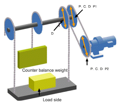
Calculation for lifting unit drive
In the case of frequent start-stop operation, consider the load factor listed in a calalog.
Click here
to refer the load factor listed in a catalog.
Summary of the machine
1.1 Specification of machine
① Gross weight of load side
W =
kg
② Total weight of counter balance weight
C =
kg
③ Total weight of wire rope or chain
Y =
kg
④ Diameter of dram, or P.C.D of main sprocket wheel
D =
mm
1.2. Connecting method with reducer (gearmotor)
Using a sprocket wheel or a gear
Shaft direct connection
⑤ P.C.D of a sprocket wheel or a gear
P1 =
mm
⑥ P.C.D of a sprocket wheel or a gear
P2 =
mm
Decision of any condition for input & output
① Motor speed
N =
1500
1000
1800
1200
r/min
Motor speed with commercial power
50Hz 4P:1500r/min 6P:1000r/min
60Hz 4P:1800r/min 6P:1200r/min
In the case of inverter drive, the base motor speed is 1800r/min.
Decision of conveyance speed and reduction ratio
In the case that conveyance speed is decided
In the case that redcution ratio is decided
① Speed
V =
m/min
② Reduction ratio (calculated value at ①)
Z =
Z=π×D×N×P2/(1000×P1×V)
① Reduction ratio
Z =
② Speed(calculated value at ①)
V =
m/min
V=π×D×N×P2/(1000×P1×Z)
Caluclation of lead torque
4.1 Input of efficiency
① Efficiency of reducer and gearmotor
η
c
=
参考
CYCLO DRIVE 1stage type: η
c
=0.9
CYCLO DRIVE 2stage type: η
c
=0.8
HYPONIC DRIVE η
c
=0.85
② Efficiency of the sprocket wheel or the gear
η
g
=
(Reference values)
一般的には η
g
=0.9
In the case of shaft direct connection η
g
=1
4.2 Calculation result (load torque and motor power)
③ Caluclation of load torque
Tf =
N・m
Tf=(W+Y-C)×g×D×P2/(2000×P1×Z×ηc×ηg)
④ Conversion from load torque Tf to motor-power Pf
Pf =
kW
Pf=Tf×N/9550
Calculation of load moment of inertia
5.1 Calculation result (load moment of inertia)
① Moment of inertia of carrier and chain or belt (Converted in a motor shaft)
JW =
kg・m
2
JW=((W+Y+C)/4)×(D×P2)
2
/(1000×P1×Z)
2
5.2 Calculating the moment of inertia of total load
Input mass of sprocket, drum, gear etc.
Weight of sprocket, drum, gear etc is unknown
② Total weight of sprocket wheel and gear (P1)
Wp1 =
kg
③ Total weight of sprocket wheel and gear (P2)
Wp2 =
kg
④ Moment of inertia of sprocket wheel or gear (Converted in a motor shaft)
Jp1 =
kg・m
2
Jp1=(Wp1/8)×(P1×P2)
2
/(1000×P1×Z)
2
Jp2 =
kg・m
2
p2=(Wp2/8)×P2
2
/(1000×Z)
2
② Moment of inertia of sprocket wheel or gear (Converted in a motor shaft)
Jp1+Jp2 =
kg・m
2
Jp2=(Wp2/8)×P2
2
/(1000×Z)
2
⑤ The moment of inertia of total load (Converted in a motor shaft)
Jf =
kg・m
2
Jf=JW+Jp1+Jp2 or JW+JW×0.2
Temporary selection of motor
6.1 Type of motor
Standard type
For inverter drive
① Motor power
0.015
0.025
0.04
0.06
0.09
0.1
0.2
0.25
0.4
0.55
0.75
1.1
1.5
2.2
3.0
3.7
5.5
7.5
11
15
18.5
22
30
37
45
55
kW ×
4
4
P
Select bigger motor power than the value of 4②
② Brake
Without
With
③ Pattern of operation
Commercial power supply
Inverter control
Power: 3-phase 200V 50Hz
Power: 3-phase 200V 60Hz
Power: 3-phase 220V 60Hz
Power: 3-phase 400V 50Hz
Power: 3-phase 400V 60Hz
Power: 3-phase 440V 60Hz
Power: Single-phase 100V 50Hz
Power: Single-phase 100V 60Hz
Power: Single-phase 200V 50Hz
Power: Single-phase 200V 60Hz
Power: Single-phase reversible 100V 50Hz
Power: Single-phase reversible 100V 60Hz
Pattern of operation
Commercial power supply
A =
sec
B =
sec
Inverter control
C =
sec
D =
sec
E =
sec
B =
sec
Calculation